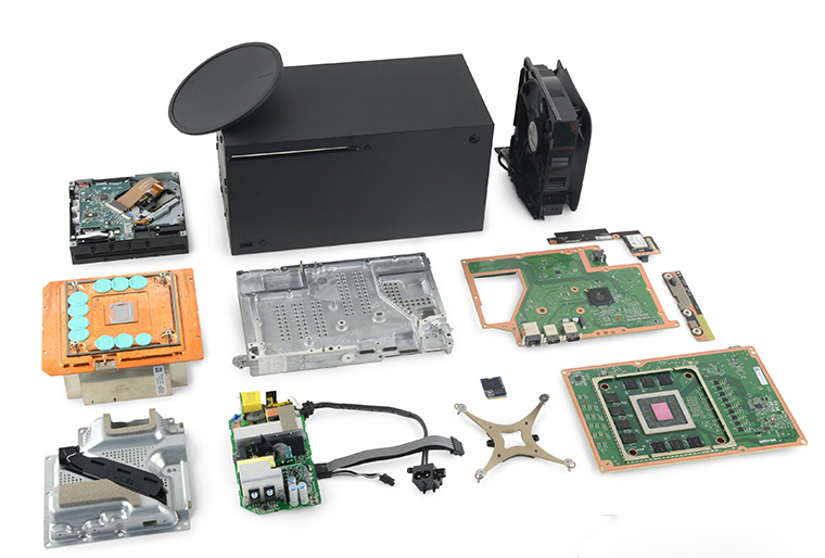
The design on this version isn’t much different than the 1708 so far, I haven’t dug into it yet though. Will update TP spots and yadda yadda yadda when I get the time to poke around with all of that.
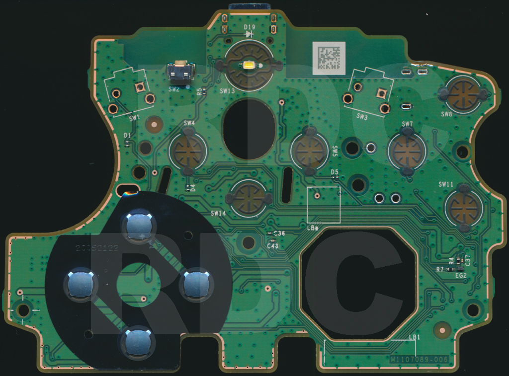
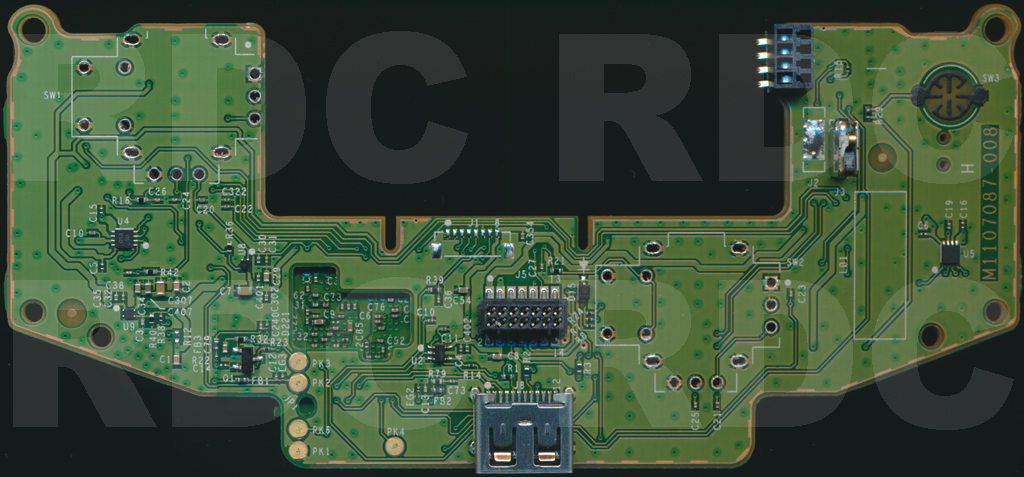
1914 BUTTON/POWER BOARD TOP
1914 BUTTON/POWER BOARD BOTTOM
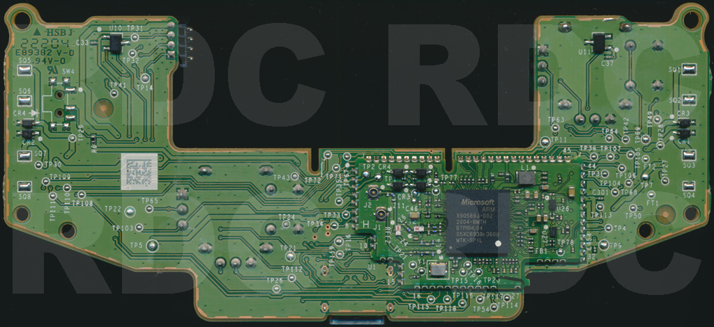
1914 MCU BOARD TOP
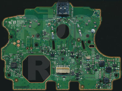
1914 MCU BOARD BOTTOM
J3/J5 Connector Pinout
1 – 3.6v
2 – GU (thru D27) Only Guide will work if J3/J5 pin 2 is used for new/alternate Guide button. Use Cathode side of D27 on Power/Button board or controller will not power on when it’s pressed.
3 –
4 – 3.3v
5 –
6 – LED
7 –
8 – D+
9 – ~RESET
10 – D-
11 –
12 – VBUS
13 –
14 – GND
TEST POINTS on BUTTON/POWER Board (some)
TP14 – DR
TP15 – DL
TP16 – DU
TP18 – SY
TP19 – LB
TP20 – RB
TP21 – A
TP22 – X
TP23 – Y
TP24 – MN
TP25 – VW
TP27 – CC1 (thru R55*) CC2 (thru R56*) *not installed
TP28 – LED
TP35 – 3.3v
TP37 – 3.6v
TP38 – 5v
TP39 – SH (Share)
TP40 – LED (Anode, after R5)
TP41 – LED (Cathode)
TP42 – LED Control (to Base/Gate of Q3)
TP43 – GU
TP44 – DD
TEST POINTS on MCU Board (some)
FT1 – GND
TP21 – GND
TP22 – GND
TP26 – GND
TP27 – LT MOTOR+
TP28 – HEAVY MOTOR+
TP29 – RT MOTOR+
TP30 – LIGHT MOTOR+
TP41 – B (thru 100ohm)
TP42 – LSC (thru R16, 33ohm)
TP43 – RSC (thru R21, 33ohm)
TP49 – 3.3v, 125Hz, 17% Duty (Hall Sensor VCC)
TP63 – LSY
TP64 – LSX
TP65 – RSY
TP67 – RT
TP68 – LT
TP103 – AN+
TP112 – RSX